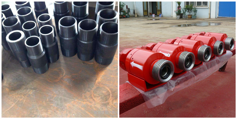
Check Valve
Features:
Valve body is machined of alloy steel forging with a stronger machinery properties and reliable performance.
Bonnet is connected with valve body with bolt, and it decreases the corrosion against bolt and bolt hole from acid medium as well as bolt loading .
Operation instruction:
According to medium flow direction and by the flow direction indicating plate of the valve, the valve is installed. As positive flowing,The medium lifts the valve core and pass easily; If no positive medium pressure, valve core will self-shut off valve gate under self-weight and spring? tensile force. the back medium flowing stop.

Maintenances:
The valve should be placed in the dry and airy room,and the inlet and outlet are sealed properly.
When the product is stored, the end flanges should be coated by oil against rust and dirt pollution.
The valve-core and the valve- seat examined every in a well time. The attrition rate will decide whether they are used by upset or are replaced .
Every seal element is replaced according to its examination.
There is a bit leak at a couple of seals of valve ,and the sealing-face may have scratch or wear .Renovation will be done under face-off and ground finish .
As leak appears at the middle one of the valve bores, ring gasket should be replaced.
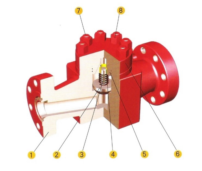
Schematic diagram of check valve:

| Item | Component | Qty | Material | Code |
| 1 | Body | 1 | 4130 | SH- -CV- -xx-xx-01. |
| 2 | Valve Core | 1 | 4130 | SH- -CV- -xx-xx-02. |
| 3 | Spring | 1 | 1566 | SH- -CV- -xx-xx-03. |
| 4 | Bushing | 1 | Cuprum | SH- -CV- -xx-xx-04. |
| 5 | O- Ring | 2 | | SH- -CV- -xx-xx-05. |
| 6 | Bonnet | 1 | 4130 | SH- -CV- -xx-xx-06. |
| 7 | Stud | 8 | 4130 | SH- -CV- -xx-xx-07. |
| 8 | Nut | 8 | 5140 | SH- -CV- -xx-xx-08. |
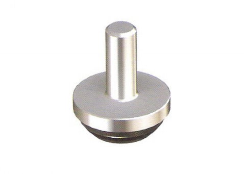
Schematic diagram of check valve disc structure:


